RasPiCommPlus PLC – Automation
Posted by on February 7, 2015

PLC Programming GUI
This is a very short but also very exciting blogpost about our recent work on the RasPiCommPlus.
We just integrated the iec2c compiler by matiec to the RasPiCommPlus. What it does is pretty amazing: It compiles ST (structured text) or IL code (both IEC 61131-3 compliant) used for PLC programming to C code, which we compile and program to the ARM processor. Voila, you now have a real PLC running independently of the Raspberry Pi (you can disconnect the Pi and the PLC keeps running). But we also developed a Linux driver to read PLC variables and change the state of the PLC (start, stop) or read the cycle time.
You can also use Beremiz to generate the ST code if you prefer using the graphical ladder diagram for programming. Debugging with the Beremiz GUI is not yet possible but planned.
Currently, only digital I/Os are working, but we are working on integrating the serial devices too, so you can also send and receive data through the RS-232, RS-485 and the other modules.
The digital I/Os are still accessible through the Linux drivers, even when they are in use by the PLC. This might be different with the serial ports when implemented, but maybe we still use the drivers to monitor/debug serial communication when the module is occupied by the PLC. If the PLC does not use the serial module the kernel driver still works as expected.
We will introduce an option to the build.amesocn.com site to link in PLC code, but building locally on the Pi will also be possible. The driver source (also available through build.amescon.com) will then be combined with the PLC code, compiled and programmed directly from the Pi.
So in places where you used Siemens S7 PLCs or similar you now can use the RasPiCommPlus which is not only more flexible but also cheaper and with the new Raspberry Pi B 2 you have a powerful Linux machine capable of logging machine data to databases or running websites for monitoring or configuration (for example by using the RasPiCommPlus Web API)
RasPiComm+ Indiegogo Campain Start
Posted by on November 12, 2014
We started our Indiegogo campain, have a look:
http://www.indiegogo.com/projects/raspicommplus-all-in-one-raspberry-pi-extension
Have a look and spread the word!
RasPiComm+ finalized, Indiegogo campain preparation
Posted by on October 30, 2014
It has been some time since the last post about the RasPiComm+, but be assured, we were very busy and have put huge efforts in finalizing the product and I can now proudly say that we are ready for production.
We are launching a Indiegogo campaign mid-November 2014, so please spread the word!

So here is an update and/or introduction for those who have not heard about the RasPiComm+ before.
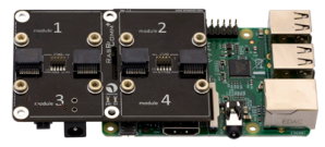
The RasPiComm+ is an extension platform for the Raspberry Pi which offers an arbitrary combination of up to 4 modules. The huge difference to other extension boards out there is not only the flexibility of using exactly the modules you need but also that all modules come with full linux driver support. I’ll do separate posts showing that in detail, including videos.
Connection to the Raspberry Pi
You may have noticed that the header has 2×14 pins which is uncommon. That is easy to explain: The RasPiComm+ is backwards compatible to the Raspberry Pi B, but also supports the EEPROM functionality for the Raspberry Pi B+, so the inner 2 pins are unused on the B version. When you are using the B+ version, the EEPROM of the RasPiComm+ can be accessed from the Raspberry Pi.
So how does it work now?
 You just plug in the modules you need (see below for available modules).
The easiest way to install the firmware and drivers is in online (the Raspberry Pi is connected to the Internet). Just run the script “./rpc+setup” and you’re done. You can now access serial devices via /dev/rttyRPC+0 to /dev/rttyRPC+3 depending on the module slot. I/Os are mapped to /sys/class/gpio just like the GPIOs of the Raspberry Pi are. That means you can reuse software that access the GPIOs of the Raspberry Pi directly. Special interfaces which are not digital pins or serial devices (like for example analog inputs or displays) are mapped in files in the /proc/rpc+/module1-3 folders. See the documentation of your modules to see how to access the resources from the Raspberry Pi. In the next posts I will show you some examples on how to use various modules, from I/Os, serial ports, sending and receiving SMS messages to sending a bitmap to a Sharp Memory LCD.
What does the script do exactly?
- First, it checks if there is a base firmware on the RasPiComm+, if not it downloads and installs it
- Then it scans all 4 module slots and reads the EEPROM IDs to identify which modules are plugged in
- In the next step a request to our buildserver is made to request the firmware configuration for the ARM microcontroller and the CPLD
- The firmware is then built by our buildserver and the firmware package is downloaded, the files are stored in a local cache on your Raspberry Pi so you do not need to be online if you wish to reinstall the same configuration again
- The script programs the ARM and then the CPLD firmware
- Then the corresponding drivers are loaded
- Done. You can now access all modules from your Raspberry Pi

Web Firmware configurator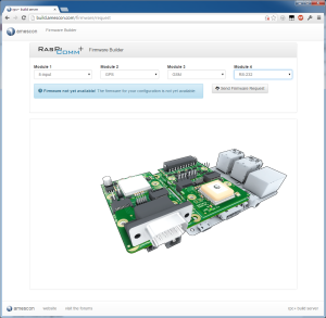

You do not need to use the automated script. You can also select the modules manually and download the firmware. This also enables you to download the sourcecode for the firmware.
If you install the Unity 3d plugin (http://unity3d.com/webplayer) you can see a beautiful 3d visualization of your configuration.
We are currently also working on a case generator. When it is ready you can also auto-generate a STL file used by 3d printers with exactly the openings you need for your selected modules. You can then print it on your 3d printer or send the file to a company offering 3d printing as a service like www.shapeways.com
The modules
We already have  quite some modules available for the start, and we are currently testing a lot more.
Modules available:
- 8 Input (5-35V)
- 8 Output (5-35V)
- 8 Analog Input (12 bit)
- 4 Relays
- RS-485/RS-485-4 wire/RS-422
- GPS
- GSM
- Profibus
- Sharp Memory Display
Modules we work on:
- 1-Wire
- 16 Isolated I/Os (24V)
- Stepper Motor
- CAN
- KNX
- 6LoWPAN
- 433MHz
- 868MHz
- 9-Axis MEMS (3 axis gyro, accelerometer and magnetometer)
Each module has an EEPROM to identify itself. The installer uses this to request the correct firmware. There is also user-space available on the EEPROM, you can store data like counter values if you want to.
 More posts are coming. In the next one I’ll quickly show you some simple scenarios how to use modules and how easy it is to script functionality.
Another post will I’ll do more in-depth explanation on how the RasPiComm+ works internally and why we made certain design decisions.
After that I will do a post on how easy you can hack the RasPiComm+ and compile your own firmware code based on the boilerplate code, to run it standalone (without the Raspberry Pi) for example or do ultra-fast switching logic with the CPLD without CPU intervention or implement additional functionality on the ARM processor with the GNU C compiler.
DIY pick and place machine
Posted by on July 18, 2013

Current status of my DIY pick and place machine
When I started developing the RasPiComm Plus I soon realized that I need the ability to manufacture smaller batches of our boards since we will have at least 10 different extension boards. I also wanted to stick to my 100% made in the EU principle.
Usually I would use my manual pick and place system to assemble prototypes. The boards are manufactured in Germany and sent to us. For larger quantities I would send the parts and boards to another company in Germany and let them assemble them. That costs almost €4.000 per 1.000 boards just for the assembling in the case of the RasPiComm. And it will take time, up to 4 weeks depending on their schedule. I needed a better solution and faster turnaround.

no more manual pick and place
Since I have a manual stencil printer and a really cool vapor phase soldering oven a pick and place machine is the missing piece of equipment to have a reasonable low volume production facility.
So those were my options:
Buy a new pick and place machine
I compared prices of various options. An US company sells a cheap pick and place, very simplistic design (no housing, aluminum profiles), for about $25.000. Shipping to Austria would have added another $2.500. The machine itself was not impressive at all. I had my doubts if it could handle 0402 relieably.
The TM220A, a $4.000 toy-grade pick and place as Dave L. Jones calls it (and I am completely with him on that) has no vision. And it does not even look like it is worth $4.000. Not an option at all.
Buy a used pick and place machine
Tempting. Ryan O’Hara bought a Quad PnP for about $16.500 (without the feeders). He talked about it on The AmpHour. It is not that easy if you are not living in the States. I cannot come over and have a look if this machine is what I want and shipping is of course awfully expensive to Austria. Another thing is the software. This price only applies to the DOS version. I like having control over the software and my processes.
Build one
Well this option has the bonus that I’d have to build something from scratch. Do you need more reasons apart from this one? I know, me neither.
Nevertheless it has to be clear that building such a machine is inevitably more expensive than buying one in the short-run. If you don’t consider your time worthless of course. But one gets better with each project, you will learn a lot and you will have a system which you understand down to the tiniest bit of wire and code, so you can tackle every problem that arises, you can adapt software and hardware to your needs. And as an entrepreneur I also keep in mind that it maybe will be a product someday, or parts of it, so I always consider these kind of projects as an investment for the future not only in terms of learning and training for me and my employees but also having working modules that can be reused later on.
Scope
I thought about my goals, what I needed and what I don’t need. First of all this should be a rapid prototyping project. I will make design decisions based on if they are practical and the effort/benefit ratio fits for me. It should not be a project which is never really usable. Since this is more a side project that a full-time project I gave myself 3 months. As I am writing this the 3 months are not over yet, so it is still in time.
I also did not want to think about automatic feeders too much for now. I knew I’ll have to redesign small areas of the machine for automatic feeder support. Until then working with belts held down by a polycarbonate shield should be sufficient for prototype quantities. For the small volume production target feeders are a must of course. So this is a compromise I make when starting this project – in the beginning I won’t have automatic feeders.
Hardware
After some hours of 3d-modelling we milled the first aluminum parts and ordered some off-the-shelf components and aluminum profiles. Milling was done with a very simple and cheap CNC, not even my good one (I got two of them). The CNC does not have a toolchanger, not even ball screw bearings. But it does its job. After that the parts went to anodization. Black of course.
-
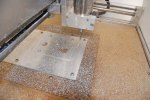
- milling…
-
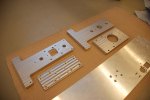
- some milled pick and place parts
-
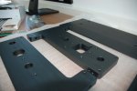
- after black anodizing
Next step: Motors. I used quite beefy stepper motors in closed-loop mode for the X and Y axis and servos for the 2 heads I planned. Part rotation is again done by a stepper motor with a hollow shaft. Two simple turning parts made from stainless steel made the pickup base for the nozzle. I glued a magnet to the bottom. I used simple fuse clips as the nozzle holders. Nozzle-changer: done.
X and Y have ball-screw bearings with a pitch of 20mm to get the speed up. With a 500 step encoder with quadrature encoding this means a positioning precision of +/- 0.09° which would be +/- 100µm. Enough for this machine. I plan to switch to BLDCs for a couple of other reasons with a 4000 step encoder which would lower that to 50µm in normal mode and 12.5µm with quadrature encoding. This is of course hypothetical, the mechanics are not that precise but still very good since I only used high quality ball bearings for X, Y and Z axis. The guides are also precision ones.
Assembing was easy, it took a couple of hours. Wiring was a bit of a pain, it took a whole day.
-
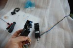
- head assembly
-
- nozzle holder
-
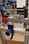
- pick and place partially assembled
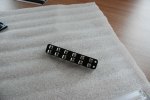
For the vision system I am using are 2560×1680 pixel USB3.0 cameras. One from the bottom for part alignment and a top camera for PCB/feeder alignment. I made a simple ringlight with 48 650nm wavelength LEDs. Funny detail: I was not able to do a circular pattern alignment of the LEDs in Altium, so I wrote a tiny Autohotkey script which allowed me to enter a number of parts and a diameter and it automatically aligned the parts correctly. Huge timesaver when you want to play around with the radius in which the parts are aligned on the PCB.
I also added a joystick to move around in the x-y plane, for testing and basic board adjustment. Fiducial recognition and board alignment should be done by camera of course, but to give the software a hint where the board is the joystick allows to move to the approximate position.
I wanted to have the top metal platform made since my CNC is too small to mill it so I asked a company what it would cost to do it for me. The price was about €1.500, too expensive for now. Thats why currently I only mounted a 10mm thick and 200mm wide aluminum sheet I had. Enough to hold my small PCBs and a couple of smd parts.
Software

Pick and Place Software
Since I already did write some code some years ago for a pick and place thing I had something to start from. Writing a gerber-file importer took me two days (I did it from scratch using the gerber file format specification from Ucamco). Martin adapted the old code and added the support for our motor drivers, our cameras as well as reading the pick and place csv files. So we had our complete software solution to load gerber and pick and place data and control our motors. Sweet!
For the vision I used OpenCV which I knew a bit. This was very straight forward, it took me under an hour to get a usable rectangle detection on an 0402 part with the rotation information. Still have to test how it will work in the real world. If I learnt anything from building machines than that in the production environment not a single thing will be as in your lab/test environment. I set the filters so that only the red light of my ringlight is captured. That way sunlight won’t screw up my detection. We have a glass roof in the office and no housing for the pick and place yet, so that was quite a good test for the relieability of the alignment algorithm.
Another cool thing when writing your own software is that it can be taylored to your specific process. Since I use GIT as my version control system (even for Altium) I want the pick and place machine to pull the project and load the PnP and gerber data. The PnP will of course have a wireless lan built in and a nice sweet touchscreen and nice GUI.
On what hardware should the software run? Raspberry Pi?
The PnP could be controlled with a Raspberry Pi with our RasPiComm+ and in the beginning I wanted to use this as a platform. But since our old software is built with WPF (windows presentation foundation, a very powerful GUI framework), porting the GUI would have been too cumbersome. The bussiness logic would be easy to port since Mono runs on the Raspberry Pi. But in terms of GUI there is simply no match for WPF out there. And I want to use a touchscreen to control the PnP. Easy to make custom UI controls with WPF, very time consuming with other technologies. And when it comes to the vision system a little ARM processor would definately slow things down. The USB 3.0 cameras are running at 15fps at full resolution, pumping 180MB/s into the OpenCV algorithms, easy for a modern CPU but not realistic for an ARM processor (there is of course no USB 3.0 support limining bandwith even further). I also considered the Xilinx Zynq since I have a ZC702 development board. I played around a little bit, attached a camera but after a day I realized thats not the way to go. In terms of development time nothing can beat C#. And CPUs are fast enough for what I needed, and power efficency is not a mayor concern here. To be up and running fast I also would have needed extremly expensive Xilinx IP which I would avoid at all costs (no pun intended). And then there is the problem with fast adoptions. I want to be able to tweak and parametrize the vision system algorithms for different part classes, easy and fast when done in pure software, hard and time-consuming when done in FPGA logic even with all the amazing IP Xilinx provides.
So in the end it is a boring mini-itx board with a 3.2GHz quad-core and 4GB of RAM. More than enough, and alltogether (including CPU, RAM, SSD and full-HD touchscreen) cheaper than the ZC702 development board alone.
Automatic Feeders
The automatic feeders are not done yet, I just have some basic design approaches. Some say they are the hardest part. I don’t know yet, my focus was to get the PnP up and running. But if its too hard I will simply buy some. Currently I only have a simple aluminum board holding down the components with a polycarbonate sheet just for initial test run purposes. Simple but it works for now. I’m still a bit struggling with the resonance of the motors, at certain speeds small parts can flip. But on one hand the resonance can be minimized by tweaking the CL-parameters of the motor controller which I have not done yet , on the other hand I still want to design proper feeders and replace the stepper motors with BLDCs. So thats not a mayor concern for now.
Next steps
My next step is tuning the pick and place process and do a video. And building feeders of course.
Here is a short speed/motor test with a joystick (no actual pick and place action yet, I’ll do that in a separate video):
UPDATE: First pick and place test with and without vision:
RasPiComm+
Posted by on April 10, 2013
Here is a quick update on the RasPiComm+ status. We are currently working hard on the Raspberry Pi drivers and hope to get the RasPiComm+ out there in Q3.

RasPiComm Plus mounted on Raspberry Pi with GSM and 16 isolated I/O extensions
The board itself is a 56x74mm 4-layer board, most components are mounted on the bottom. The top-side only features 4 edge-board connectors for the modules, power LEDs and two JTAG debugging/programming headers for the Cortex M3/M4F and the Altera MAX V CLPD.
We currently have 6 RasPiComm+ modules which we are testing:

CAN bus, RS-485, 8 inputs and 8 outputs RasPiComm+ extension boards
- 8 Input (with adjustable reference voltage, can be jumpered to 5V or 24V or fed from outside)
- 8 Outputs (5V or 24V or fed from outside)
- GSM module
- RS-485 (two RS-485 on one board)
- CAN (two CAN bus ports on one board, you’ll need the ARM Cortex-M4 option to use both simultaneously)
- 16 isolated I/O (using th iC Haus iC-JX)
The firmware of the Cortex M3/M4F (both can be populated) will provide a bridge from the extension boards to the Raspberry Pi and interface with the drivers. The ARM microcontroller can be programmed from the Raspberry Pi for power users. It will come with a fully functional firmware and does not need to be changed though. If you want do do realtime or high relieability stuff you can do this by programming the ARM microcontroller.
The CPLD is also programmable via the Raspberry Pi, so changing configurations for different extension modules is easy.

RasPiComm+ bottom side
The big metal box on the bottom side is an isolated DC/DC converter. This will be optional and powers both the RasPiComm+ and the Raspberry Pi from a 24V power supply. The battery holder is for the real-time clock backup battery for which we will also add driver support, so that the Raspberry Pi can get the current date and time.
The driver is very elegant I think. You can dynamically load and unload driver modules and they create an interface (for example /dev/ttyRPC0) to the specified module in case the module is a serial module (this applies to the GSM, RS-485 and the CAN module). This is already working quite well, we successfully sent SMS messages from the Raspberry Pi.
For the I/O modules we are looking into a driver interface similar to the Raspberry Pi GPIOs, but this is still work in progress, if you have suggestions what the best way is to implement I/Os leave a message 🙂
I will post separate articles about the RPCP extension boards to explain them in detail.
And if you have any other ideas how to make the RasPiComm+ even better let me know!
RasPiComm Plus – an early insight into the ultimate Raspberry Pi extension board
Posted by on February 25, 2013
 Our primary goal is to make the ultimate connectivity extension boards for the Rasberry Pi to connect it to the outside world. We think with the RasPiComm Plus we took the possibilities one step further.
Since I already wrote about our intention to develop a “RasPiComm Plus” I want to share details about this project in quite an early stage so you have the chance to comment on the design. We have a perfectly working prototype, so not as early as you might think now, but the RasPiComm Plus is a bit more complex than the RasPiComm, so we have quite a bit of software development work ahead of us. But first things first.
With the RasPiComm Plus we wanted to tackle some issues that are inherent to extension boards of that kind, flexibility and size being two of them. So what we did is to build an expansion board for expansion boards. Sounds complicated but it’s quite straight forward as you’ll see.
The RasPiComm Plus (our internal project name is Tiny Chameleon, you’ll see why) is a board with its own microcontroller (an ARM Cortex M3) and 4 edge-card connectors on the top side and the ICs and Raspberry Pi connector on the bottom. Now here is the cool part: You can plug up to 4 extension boards into those connectors depending on your needs. You can mount them with two screws so that the RasPiComm Plus is a wiggle-free, rock-solid customized extension board.
Here are the extension boards we want to start with:
- 8 Inputs (5-35V), switching on 1/2 of the reference voltage with hysteresis
- 8 Outputs (5-35V, 350mA/500mA peak with thermal shutdown and output transient protection/clamp diodes)
- dual RS-485
- CAN bus
- GSM module
- development board
Extension boards we are planning to make:
- Isolated inputs and outputs
- isolated RS-485
- isolated/non-isolated RS-232
- isolated CAN bus
To make these 4 connectors totally flexible we have a CPLD (complex programmable logic device) between the connectors and the microcontroller. So you are totally flexible which connector goes to which pins on the microcontroller and therefore you are able to plug any extension board in any slot!
As always, we want to provide a plug-and-play solution, so no playing around with the CPLD is needed, neither with the microprocessor, if you don’t want to. We will provide a serial driver module that will map the serial ports to /dev/tty devices as we do it with our RasPiComm board, and an API for the I/Os and the GSM module all hosted on github and on our repository for easy apt-get installation (which is also true for our RasPiComm drivers if you didn’t know yet!)
If you want to make your own microcontroller applications you can program the ARM processor directly from the Raspberry Pi via the serial port /dev/ttyAMA0 and the build-in bootloader. And if you want full control (ARM debugging and CPLD programming) you can use the JTAG headers (one for the ARM and the other one for the CPLD) to do your own custom solution. You want your outputs to react to inputs in 7 nanoseconds? No problem, program your logic into the CPLD and there is your ultra-fast “direct-wiring”.
You want a real-time system for your automation solution? Just program the ARM-processor any way you like using the extension boards mentioned above.
You need a stepper motor controller? Thats definitely on our list for further extension boards!
Here is a bottom view of the RasPiComm Plus where you can see the Raspberry Pi GPIO connector:

As you can see it uses the same piggyback approach as the RasPiComm even though it is longer extending over the borders of the Raspberry Pi. But that also has an advantage: you have 2 mounting holes and in fact you are not losing much space since the SD card of the Raspberry Pi is sticking out in this direction anyway.
Here are some features of the RasPiComm Plus:
- 74x56mm
- Real Time Clock with backup battery
- ARM Cortex-M3
- CPLD connected to the ARM, the Raspberry Pi and the 4 extension connectors
- 5V supply connector
- 24V supply connector
- 24V-5V isolated DC-DC coverter (optional)
- Raspberry Pi GPIO connector
Be aware that this is an early stage as I said, so there is no release date yet. But we would love to hear your ideas and comments on this design!
More infos about the RasPiComm Plus will follow soon so stay tuned!
Also have a look at our already availabe RasPiComm, the tiny Raspberry Pi piggyback board with RS-232, RS-485, real-time clock, joystick and more!
Use RS485 from your Raspberry Pi via /dev/ttyRPC0!
Posted by on February 25, 2013
Our RasPiComm device driver is available now! You can now use /dev/ttyRPC0 (RPC for RasPiComm) to access the RS485 port. Find the sourcecode on Github!
Go to our community forum if you have any questions!
RasPiComm Forum is online
Posted by on January 14, 2013
Our new website is online!
Have a look at www.amescon.com/forum.aspx and start discussing or asking questions about the RasPiComm extension board.
You can even win a RasPiComm if you vote on the forum:
1st place: A Raspberry Pi + RasPiComm + OLED Display
2nd place: A Raspberry Pi + RasPiComm
3rd-5th place: A RasPiComm
The winners of the contest will be announced on 01/27/2013.
RS ordered RasPiComms!
Posted by on January 7, 2013
Finally!
RS Components placed the order, we got a slot on Friday (yes, RS has timeslots, you cannot simply send your stuff).
So we already have a UPS pickup organized, RasPiComms will arrive on Friday at RS. No, it is not yet on the RS shop for preorder, no, I don’t know what they add to our price. But the good news is that the RasPiComm will be available very soon!
Big thanks here to LTEK, they “borrowed” us their account, so on RS the vendor will be LTEK for the first shipment. When our vendor account is set up we can sell directly. We had to do this because apparently it takes more than 3 months to set us up as a vendor and thanks to LTEK we do not have to wait until this process is finished.
This week, before the boards arrive at RS, our website will get its well deserved relaunch, so there will be a forum through which we will provide support.
Short RasPiComm status update
Posted by on December 20, 2012
You had to wait a long time without updates, sorry for that! We have been really busy with a lot of things including the RasPiComm.
As you probably know we have manufactured our first batch already. Sadly we still do not have the order from RS.
I’ve been to the Electronica in Munich to meet some guys from RS and we found a solution to speed up the process a little bit by placing the initial order through another company which is already listed as a supplier. That is now all in place, the RasPiComm is set up, so the next step is waiting for the order.
When we have the order we can ship the boards. So we are almost there, but I already said that a month ago.
Just wanted to let you know that we are still pushing here, and we are coming closer to shipping the boards. Thank you for your patience!
